General Purpose Input/Output (GPIO) RP2040 & ESP32#
The General Purpose Input/Output (GPIO) pins on microcontrollers like the RP2040 and ESP32 are versatile pins that can be configured as either input or output pins. They can be used to read digital signals from sensors, control LEDs, drive motors, and interface with other digital devices.

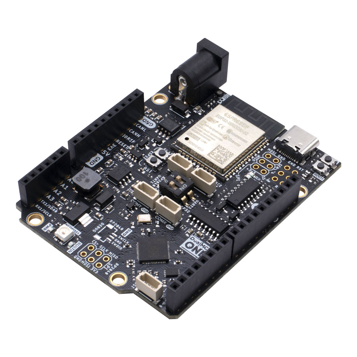
Fig. 19 DualMCU ONE board#
The DualMCU ONE development board is equipped with 22 GPIO pins, 4 of which can be used as analog inputs. The ESP32 microcontroller also has a large number of GPIO pins but these pins require a expansion board to be used.
Let’s start with a simple example: blinking an LED. This example will demonstrate how to control GPIO pins on the DualMCU ONE board using both MicroPython.
LEDs ESP32 & RP2040#
In this section, we will learn how to work an RGB LED using a microcontroller. We will learn how to use the LED to different GPIO pins and control its on and off states with a simple program.
Hardware Description#
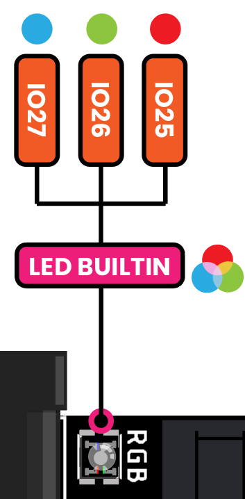
An RGB LED has three LEDs in one: red, green, and blue. You can control the color of the LED by varying the intensity of each of the LEDs. Here is an image of the RGB LED:

Fig. 20 RGB LED#
Pin Connections#
PIN |
GPIO ESP32 |
GPIO RP2040 |
|---|---|---|
BLUE |
27 |
|
RED |
25 |
25 |
GREEN |
26 |
RGB LED Code ESP32#
Tip
This code block is designed to work exclusively with the RGB LED on the DualMCU development board when using the ESP32 microcontroller.
import machine
import time

led_pin = machine.Pin(27, machine.Pin.OUT)
led_pin2 = machine.Pin(26, machine.Pin.OUT)
led_pin3 = machine.Pin(25, machine.Pin.OUT)

def loop():
    while True:
        led_pin.on()
        led_pin2.on()
        led_pin3.on()
        time.sleep(1)
        led_pin.off()
        led_pin2.off()
        led_pin3.off()
        time.sleep(1)

loop()
#define LED 25

// the setup function runs once when you press reset or power the board
void setup() {
    // initialize digital pin LED_BUILTIN as an output.
    pinMode(LED, OUTPUT);
}

// the loop function runs over and over again forever
void loop() {
    digitalWrite(LED, HIGH);   // turn the LED on (HIGH is the voltage level)
    delay(1000);                       // wait for a second
    digitalWrite(LED, LOW);    // turn the LED off by making the voltage LOW
    delay(1000);                       // wait for a second
}
LED Blink Code RP2040#
Tip
This code block is designed to work exclusively with RP2040 microcontroller on the DualMCU development board.
Caution
A single LED is connected to GPIO 25 on the RP2040 microcontroller.
import machine
import time

led = machine.Pin(25, machine.Pin.OUT)

def loop():
    while True:
        led.on()
        time.sleep(1)
        led.off()
        time.sleep(1)

loop()
#define LED 25

// the setup function runs once when you press reset or power the board
void setup() {
    // initialize digital pin LED_BUILTIN as an output.
    pinMode(LED, OUTPUT);
}

// the loop function runs over and over again forever
void loop() {
    digitalWrite(LED, HIGH);   // turn the LED on (HIGH is the voltage level)
    delay(1000);                       // wait for a second
    digitalWrite(LED, LOW);    // turn the LED off by making the voltage LOW
    delay(1000);                       // wait for a second
}
