General Board Control#
The CH552, characterized by its compact size, native USB connectivity, and 16 KB memory (with 14 KB usable), enables the creation of simple yet effective programs. This allows for greater control in implementing various applications. The choice of this microcontroller is based on its affordability, ease of connection, and compatibility with various operating systems.
Recommended Operating Conditions#
Symbol |
Description |
Range |
|---|---|---|
VUSB |
Voltage supply via USB |
3.14 to 5.255 V |
VIn |
Voltage supply from pins |
2.7 to 5.5 V |
Top |
Operating temperature |
-40 to 85 °C |
Voltage Selector#
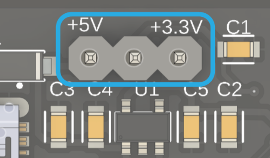
The development board utilizes a clever voltage selector system consisting of three pins and a jumper switch. The configuration of these pins determines the operating voltage of the board. By connecting the central pin to the +5V pin via the jumper, the board operates at 5V. On the other hand, by connecting the central pin to the +3.3V pin, the APK2112K regulator is activated, powering the board at 3.3V. It is crucial to ensure that the jumper switch is in the correct position according to the desired voltage to avoid possible damage to modules, components, and the board itself.

Fig. 12 USB Connector#
JST Connectors#
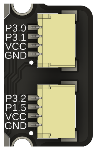
The board features two 1mm JST connectors, linked to different pins. The first connector directly connects to GPIO 3.0 and 3.1 of the microcontroller, while the second one is linked to pins 3.2 and 1.5. Both connectors operate in parallel to the selected power supply voltage via the jumper switch. These connectors are compatible with QWIIC, STEMMA QT, or similar pin distribution protocols. It is essential to verify that the selector voltage matches the system voltage to avoid circuit damage. Additionally, these connectors allow the board to be powered and offer functionalities such as PWM and serial communication.

Fig. 13 JST Connectors#
Built-In LEDs#
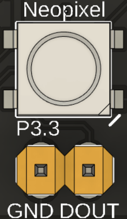
The board features two LEDs directly linked to the microcontroller. The first one is connected to pin 3.4, while the second one is a Neopixel LED connected to pin 3.3. This Neopixel provides an output with two headers, one connected to the data output and the other to the board’s ground, allowing for the external connection of more LEDs. To use this output, simply connect the DOUT pin to the DIN pin of the next LED in the row. As for power supply, you can use the VCC pin, provided that the external LEDs can operate at this voltage. Otherwise, it will be necessary to power them using an external source.

Fig. 14 Neopixel LED#
