Exercises with the DualMCU Board - MicroPython
4. Temperature Sensor
Objective
Obtain the current temperature reading from the analog sensor LM35 and demonstrate the results by monitoring the serial output in Thonny IDE.
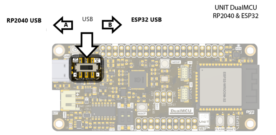
NOTE In this practices, you will use the microcontroller RP2040.
Descriptions
This practice emphasizes the use of the LM35 analog sensor for current temperature measurement. The LM35 sensor is chosen for its versatility and easy integration with various development boards. This board is suitable for educational environments and electronics projects, and it is compatible with multiple platforms such as Arduino, Raspberry Pi, NodeMCU, ESP32, and other devices with analog pins.
The selection of the LM35 focuses on temperature measurement precision and its straightforward connectivity. As an analog sensor, it allows continuous temperature readings, making it an ideal choice for creating user-friendly interfaces with specific microcontrollers. This ease of integration is beneficial for projects involving temperature monitoring, climate control, and other applications that require real-time thermal measurements.
While introducing the LM34 sensor for practice, our focus is on understanding the process of analog readings and showcasing the results in the Thonny IDE shell. The accompanying code serves as an example, empowering users to implement functions suitable for devices that demand access and adaptation across diverse platforms. This approach enhances versatility and fosters a broad range of experiences in working with analog sensors.
ADC Descriptions
The use of the ADC class offers an interface to convert analog signals to digital, ultimately providing a singular capture and transforming a continuous voltage into a discrete digital value. The ADC class is found within the machine module and can be imported in the following manner:
from machine import ADC

adc = ADC(pin)        # create an ADC object acting on a pin
val = adc.read_u16()  # read a raw analog value in the range 0-65535
val = adc.read_uv()   # read an analog value in microvolts
- For more information, refer to the Official Documentation.
- You can also explore available examples for the ADC in the DualMCU Board Repository.
Materials
For using the ESP32 microcontroller, you need the additional materials mentioned before, including:
- 2x LEDs
- 2x Resistors 220Ω
Connection Diagram
NOTE: Remember that when working with the DualMCU board, you can interchange between microcontrollers using interrupt-driven changes.

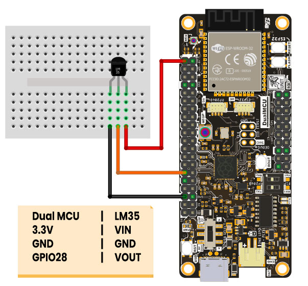
To proceed, here is the diagram illustrating the connection between the LM35 temperature sensor and the DualMCU development board using the RP2040 microcontroller.

If you prentent do the practicies using the microcontroller ESP32 use the next configuration:

Code
The following codes provide examples of how to use the LM35 temperature sensor with two different microcontrollers (RP2040 & ESP32). In both cases, configure the analog input to read the output from LM35 and obtain the temperature in degrees Celsius.
'''
Unit Electronics 2024
          (o_
   (o_    //\
   (/)_   V_/_
   tested code mark
   version: 0.0.1
   revision: 0.0.1
    RP2040
'''
import machine
import time

# Configure the analog input pin to read the LM35 sensor output

pin_lm35 = machine.Pin(28, machine.Pin.IN)
adc = machine.ADC(pin_lm35)

while True:
   # Read the LM35 sensor value in millivolts
   lm35_output_mv = adc.read_u16() * 3.3 / 65535 * 1000
   # Convert the value to Celsius using the formula
   temperature_celsius = (lm35_output_mv - 500) / 10
   # Print the temperature in Celsius
   print("Temperature: {:.2f} °C".format(temperature_celsius))
   # Wait for a second before taking the next reading

   time.sleep(1)
The code for RP2040 utilizes MicroPython and Thonny to print temperature readings on a serial monitor. It sets the analog input pin, reads the value from LM35, ensuring continuous readings with a one-second interval wait.
'''
Unit Electronics 2024
       (o_
(o_    //\
(/)_   V_/_

Version: 0.0.1
Revision: 0.0.1
ESP32
'''

import machine
import time

# Configure ADC input on pin 36
adc = machine.ADC(machine.Pin(36))
# Set the voltage reading range to 0-3.3V
adc.atten(machine.ADC.ATTN_11DB)
# Set the reading range to 0-4095
adc.width(machine.ADC.WIDTH_12BIT)

# Configure pin 2 as output
led = machine.Pin(2, machine.Pin.OUT)
# Configure pin 25 as output
led2 = machine.Pin(25, machine.Pin.OUT)

# Start infinite loop
while True:
   # Read ADC value
   value = adc.read()
   # Print ADC value
   print(value)
   # If the value is greater than 2000, turn on the LED
   if value > 2000:
       led.value(1)
       led2.value(0)
   # If the value is less than 2000, turn on the other LED
   else:
       led.value(0)
       led2.value(1)
   # Wait for 1 second
   time.sleep(1)
In the case of the ESP32, the code also configures the analog input for a specific pin. However, in this scenario, it prints the readings on the serial monitor and uses the information to control two LEDs. Depending on whether the reading is greater than or less than 2000, it turns the LEDs on or off, providing a visual feedback. The infinite loop ensures the continuous reading and control of LEDs with a one-second interval. This code illustrates how to utilize sensor information to generate additional visual actions.
Results
You can observe the temperature in degrees Celsius by monitoring the serial output.

Conclusions
This practice allowed for practical insights into reading analog temperature sensors and configuring the ADC in microcontrollers. It demonstrated how these microcontrollers can not only read data but also interact with external devices. Such capabilities are fundamental for developing projects that involve the measurement and control of analog variables in electronic environments.
NOTE: Keep in mind that the presented codes are only examples and may require configuration adjustments according to specific needs and requirements.
Continue with the course Servo Control
- License The code presented in this repository is licensed under the GNU General Public License (GPL) version 3.0.
⌨️ with ❤️ from UNIT-Electronics 😊