Exercises with DualMCU - MicroPython
10. OLED Control (I2C)
Objective
The objective of this practice is to use a microcontroller from DualMCU to display information on an OLED screen.
NOTA In this practices, you will use the microcontroller ESP32.
Description
Illustrate relevant data in an easily understandable format and personalize it for display on an OLED screen in three different phases:
- Load the library for using the OLED screen SSD1306.
- Display text information on the screen.
- Create a counter to update with the ability to configure time and send data to display real-time sensor readings, such as temperature, humidity, air quality, etc., from the previous practices.
Additionally, mention that I2C communication is used as the communication protocol between the OLED screen and the DualMCU board. The proposal is to use any sensor to display its data on the screen.
Materials
- 1x UNIT DualMCU board
- 1x OLED screen
- 1x Protoboard
- 1x Cables
- 1x Cables Dupont
Connection Diagram
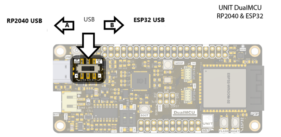
NOTE Remember that when working with the DualMCU, you can switch between microcontrollers using the change switch. For this practice, we will only use the ESP32 microcontroller, so you should switch the change switch to position “B”.
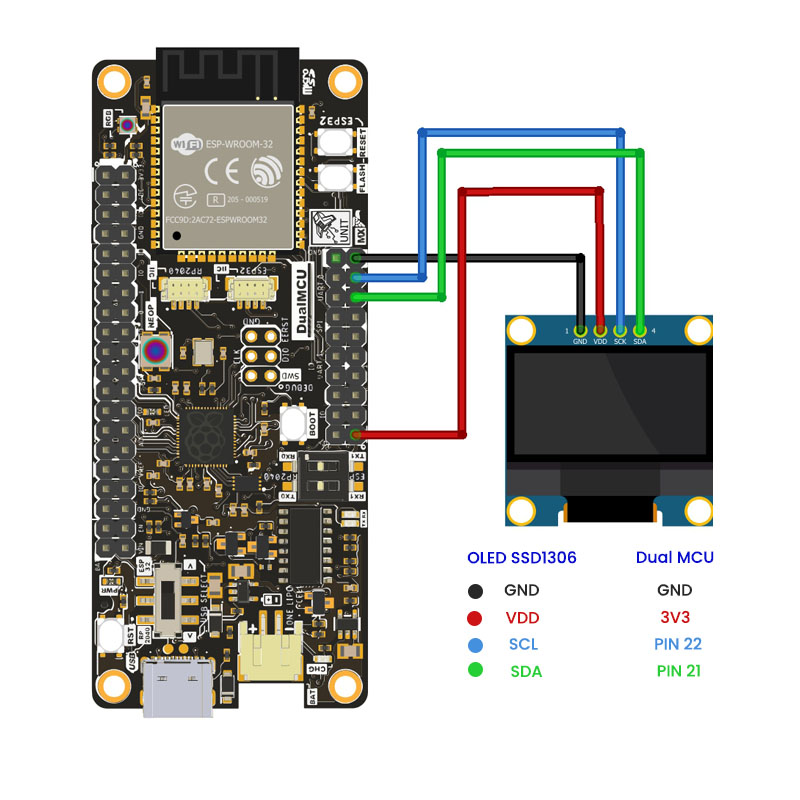
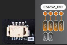
The next diagram illustrates the communication between one of the two microcontrollers and the ability to display a default text on the OLED screen.
Software
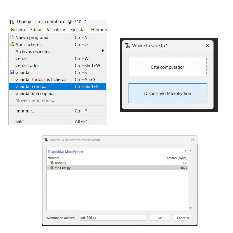
To simplify programming with OLED screen, use a specific library for OLED control. Here is an alternative for easy control. Copy or download the code and save the file as ssd1306.py on the DualMCU board.
# MicroPython SSD1306 OLED driver, I2C and SPI interfaces

from micropython import const
import framebuf


# register definitions
SET_CONTRAST = const(0x81)
SET_ENTIRE_ON = const(0xA4)
SET_NORM_INV = const(0xA6)
SET_DISP = const(0xAE)
SET_MEM_ADDR = const(0x20)
SET_COL_ADDR = const(0x21)
SET_PAGE_ADDR = const(0x22)
SET_DISP_START_LINE = const(0x40)
SET_SEG_REMAP = const(0xA0)
SET_MUX_RATIO = const(0xA8)
SET_COM_OUT_DIR = const(0xC0)
SET_DISP_OFFSET = const(0xD3)
SET_COM_PIN_CFG = const(0xDA)
SET_DISP_CLK_DIV = const(0xD5)
SET_PRECHARGE = const(0xD9)
SET_VCOM_DESEL = const(0xDB)
SET_CHARGE_PUMP = const(0x8D)

# Subclassing FrameBuffer provides support for graphics primitives
# http://docs.micropython.org/en/latest/pyboard/library/framebuf.html
class SSD1306(framebuf.FrameBuffer):
    def __init__(self, width, height, external_vcc):
        self.width = width
        self.height = height
        self.external_vcc = external_vcc
        self.pages = self.height // 8
        self.buffer = bytearray(self.pages * self.width)
        super().__init__(self.buffer, self.width, self.height, framebuf.MONO_VLSB)
        self.init_display()

    def init_display(self):
        for cmd in (
            SET_DISP | 0x00,  # off
            # address setting
            SET_MEM_ADDR,
            0x00,  # horizontal
            # resolution and layout
            SET_DISP_START_LINE | 0x00,
            SET_SEG_REMAP | 0x01,  # column addr 127 mapped to SEG0
            SET_MUX_RATIO,
            self.height - 1,
            SET_COM_OUT_DIR | 0x08,  # scan from COM[N] to COM0
            SET_DISP_OFFSET,
            0x00,
            SET_COM_PIN_CFG,
            0x02 if self.width > 2 * self.height else 0x12,
            # timing and driving scheme
            SET_DISP_CLK_DIV,
            0x80,
            SET_PRECHARGE,
            0x22 if self.external_vcc else 0xF1,
            SET_VCOM_DESEL,
            0x30,  # 0.83*Vcc
            # display
            SET_CONTRAST,
            0xFF,  # maximum
            SET_ENTIRE_ON,  # output follows RAM contents
            SET_NORM_INV,  # not inverted
            # charge pump
            SET_CHARGE_PUMP,
            0x10 if self.external_vcc else 0x14,
            SET_DISP | 0x01,
        ):  # on
            self.write_cmd(cmd)
        self.fill(0)
        self.show()

    def poweroff(self):
        self.write_cmd(SET_DISP | 0x00)

    def poweron(self):
        self.write_cmd(SET_DISP | 0x01)

    def contrast(self, contrast):
        self.write_cmd(SET_CONTRAST)
        self.write_cmd(contrast)

    def invert(self, invert):
        self.write_cmd(SET_NORM_INV | (invert & 1))

    def show(self):
        x0 = 0
        x1 = self.width - 1
        if self.width == 64:
            # displays with width of 64 pixels are shifted by 32
            x0 += 32
            x1 += 32
        self.write_cmd(SET_COL_ADDR)
        self.write_cmd(x0)
        self.write_cmd(x1)
        self.write_cmd(SET_PAGE_ADDR)
        self.write_cmd(0)
        self.write_cmd(self.pages - 1)
        self.write_data(self.buffer)


class SSD1306_I2C(SSD1306):
    def __init__(self, width, height, i2c, addr=0x3C, external_vcc=False):
        self.i2c = i2c
        self.addr = addr
        self.temp = bytearray(2)
        self.write_list = [b"\x40", None]  # Co=0, D/C#=1
        super().__init__(width, height, external_vcc)

    def write_cmd(self, cmd):
        self.temp[0] = 0x80  # Co=1, D/C#=0
        self.temp[1] = cmd
        self.i2c.writeto(self.addr, self.temp)

    def write_data(self, buf):
        self.write_list[1] = buf
        self.i2c.writevto(self.addr, self.write_list)


class SSD1306_SPI(SSD1306):
    def __init__(self, width, height, spi, dc, res, cs, external_vcc=False):
        self.rate = 10 * 1024 * 1024
        dc.init(dc.OUT, value=0)
        res.init(res.OUT, value=0)
        cs.init(cs.OUT, value=1)
        self.spi = spi
        self.dc = dc
        self.res = res
        self.cs = cs
        import time

        self.res(1)
        time.sleep_ms(1)
        self.res(0)
        time.sleep_ms(10)
        self.res(1)
        super().__init__(width, height, external_vcc)

    def write_cmd(self, cmd):
        self.spi.init(baudrate=self.rate, polarity=0, phase=0)
        self.cs(1)
        self.dc(0)
        self.cs(0)
        self.spi.write(bytearray([cmd]))
        self.cs(1)

    def write_data(self, buf):
        self.spi.init(baudrate=self.rate, polarity=0, phase=0)
        self.cs(1)
        self.dc(1)
        self.cs(0)
        self.spi.write(buf)
        self.cs(1)
This source file is originally extracted from the micropython-ssd1306 repository by Stefan Lehmann.
To save the library code on the DualMCU board, you should use the name ssd1306.py
Code
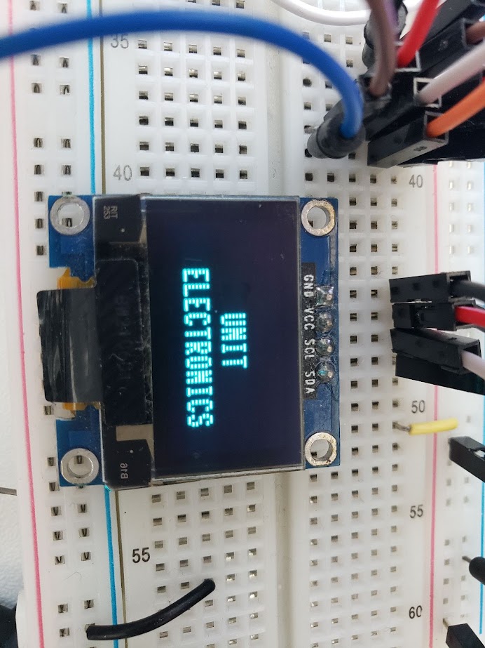
Once you have saved the program as instructed before, proceed to open a new file for programming. Use the following code, and the display will show the text “UNIT ELECTRONICS”:
'''
Unit Electronics 2023
          (o_
   (o_    //\
   (/)_   V_/_
tested code mark
   version: 0.0.1
   revision: 0.0.1

'''

import machine
from ssd1306 import SSD1306_I2C

i2c = machine.I2C(sda=machine.Pin(22), scl=machine.Pin(21))

oled = SSD1306_I2C(128, 32, i2c)

oled.fill(1)
oled.show()

oled.fill(0)
oled.show()
oled.text('UNIT', 50, 10)
oled.text('ELECTRONICS', 25, 20)

oled.show()
The next image can illustrate the test of functionality.
NOTE: Keep in mind that the presented codes are only examples and may require configuration adjustments according to specific needs and requirements.
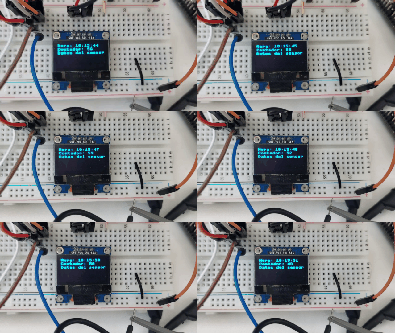
Now it will be your turn to display information from a sensor. Additionally, we share with you a code where you can obtain the following functions:
- Display the current system time and format it in digital clock format.
- Create a function for a countdown timer that accepts input time.
- Initialize, read data from environmental sensors (of your choice), and display the data on the screen.
Keep in mind that this is just a framework, and you will need to implement the getCurrentTime, createCountdown, and readSensorData functions according to your needs. You will also need to include the appropriate libraries for your microcontroller and sensors.
from machine import Pin, I2C
import ssd1306
import time

# Inicializar I2C
i2c = machine.I2C(0, scl=machine.Pin(22), sda=machine.Pin(21))
count = 100
segundos = 0
minutos = 15
horas = 10
# Inicializar la pantalla OLED
display = ssd1306.SSD1306_I2C(128, 64, i2c)

def get_current_time():
    global segundos
    global minutos
    global horas
    # Incrementar el contador de segundos
    segundos += 1

    # Verificar si ha pasado un minuto (60 segundos)
    if segundos == 60:
        segundos = 0  # Reiniciar los segundos
        minutos += 1   # Incrementar el contador de minutos

        # Verificar si ha pasado una hora (60 minutos)
        if minutos == 60:
            minutos = 0  # Reiniciar los minutos
            horas += 1    # Incrementar el contador de horas

            # Verificar si ha pasado un día (24 horas)
            if horas == 24:
                horas = 0  # Reiniciar las horas

    return segundos, minutos, horas


def create_countdown():
    global count
    if count <= 0:
        count =100
        raise ValueError("El tiempo del contador debe ser mayor que cero")
    count =count -1

    return count

def read_sensor_data():
    # Implementar la función para leer los datos de los sensores ambientales
    pass


# Obtener la hora actual
# Ejemplo de uso


while True:
    sec,minu, hour  = get_current_time()

    # Crear un contador regresivo
    countdown = create_countdown()  # 10 segundos para el ejemplo

    # Leer los datos de los sensores ambientales
    sensor_data = read_sensor_data()

    # Mostrar los datos en la pantalla OLED
    display.fill(0)
    display.text('Hora: '+ str(hour)+":"+str(minu)+":" + str(sec), 0, 0)
    display.text('Contador: ' + str(countdown), 0, 10)
    display.text('Datos del sensor: ' + str(sensor_data), 0, 20)
    display.show()

    time.sleep(1)
Conclusions
During the development of the practice, the successful configuration of I2C communication with the OLED screen was demonstrated, emphasizing the importance of using a library compatible with the device used. It is crucial to consider the specific purpose of the system, as it can adapt to both analog and digital sensors.
In this context, it is encouraged to replicate the same practice using the RP2040 microcontroller, as the QWIIC connector is available to facilitate the connection. It is important to adjust the I2C port configuration according to the corresponding pins of the RP2040.
NOTE: Keep in mind that the presented codes are only examples and may require configuration adjustments according to specific needs and requirements.
Continue with the course wireless communication
- Licencia The code presented in this repository is licensed under the GNU General Public License (GPL) version 3.0.
⌨️ with ❤️ from UNIT-Electronics 😊