DualMCU Introduction - MicroPython
General Description
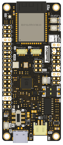
The DualMCU module represents a powerful platform that combines the Raspberry Pi RP2040 and the Espressif ESP32 WROOM chip, creating an efficient device. This design incorporates dual Arm® Cortex®-M0+ 32-bit cores, providing a robust foundation for IoT projects with Bluetooth and Wi-Fi connectivity.
In terms of processing power, the DualMCU integrates two 32-bit microprocessors: a Cortex M0+ from Raspberry RP2040 operating at 133 MHz and an Espressif ESP32 running at up to 240 MHz. This configuration allows for the maximum capabilities of both microcontrollers on a single compact board. With a PCB size of 36 mm x 84 mm, utilizing surface-mount technology, it ensures low power consumption.
For information on resources, it is recommended to refer to the official repository.
In the context of technical features, the DualMCU stands out as a unique development board in its class, showcasing unparalleled capabilities.
 | Manufacturer: UNIT ELECTRONICS PCB Color: Black Dimensions: 84mm x 36mm x 6.6mm Weight: 22.57g MCUs: RP2040 Dual Core + ESP32 WROOM-32E USB to UART: CH340C Connectors: 2 x I2C JST-SH Pitch 1mm, 1 MicroSD, USB Type C, and JST-SH 2p Pitch 2mm: Battery Connection. Includes: Double 2.54mm Male Header Strip (2×3, 2×20 pins) Memory: W25Q16JVUXIQ 2MB NOR Flash, 532MHz Quad SPI, and 66MB/S Continuous Data Transfer Rate. Power: 3.3V LDO 600mA, 3.3V Power/Enable pin, VUSB Output/VIN: 3.2 to 6V DC, Interface for charging 200mA batteries with built-in LED. Switch: Power Switch, USB Communication Selector, DIP Switch for UART communication, RESET Button, and Bootloader for quick restarts of RP2040. RESET and FLASH/BOOT Button. LEDs: WS2812B NeoPixel RGB LEDs connected to RP2040 GPIO, Common-cathode RGB LED connected to ESP32 GPIO, and Built-in LED: General-purpose LED connected to RP2040 GPIO25. MICROSD CARD: Connection to ESP32 and Communication Interface: VSPI. |
Features
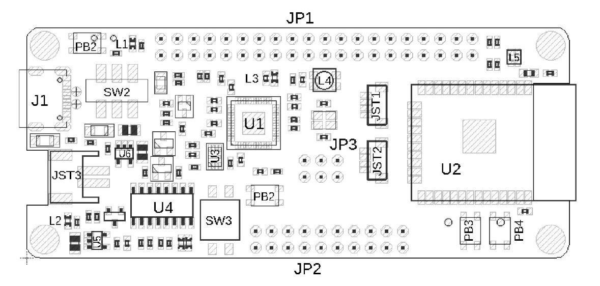
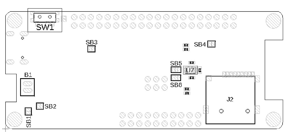
Now, let’s focus on the layout of the board elements, as it is crucial to understand the location of each component for ease of use.
Front View
| Ref. | Description | Ref. | Description |
|---|---|---|---|
| U1 | Raspberry pi RP2040 Microcontroller | U4 | CH340C USB bus convert IC |
| U2 | Espressif ESP32 WROOM Wi-Fi/Bluetooth® Module | U5 | MCP73831 Battery Charge Management IC |
| U3 | W25Q16JVUXIQ 2MB Flash IC | U6 | AP2112K 3v3 LDO Voltage Regulator |
| L1 | Power On LED | L2 | Charge LED |
| L3 | Builtin LED (GPIO25) | L4 | WS2812B LED |
| L5 | RGB 2020 LED | J1 | Male USB Type C Connector |
| PB1 | RP2040 Reset Button | PB2 | RP2040 Boot Button |
| PB3 | ESP32 Flash Button | PB4 | ESP32 Reset Button |
| JP1 | RP2040 GPIO Header | JP2 | ESP32 GPIO Header |
| JP3 | RP2040 (SWD) Debug Header | JST1 | RP2040 I2C JST Connector |
| JST2 | ESP32 I2C JST Conector | JST3 | JST Connector for LiPo Battery |
| SW2 | USB Communication Selector | SW3 | UART DIP Switch |
Back View
| Ref. | Description | Ref. | Description |
|---|---|---|---|
| U7 | Support for the ATECC608A-MAHDA-T Crypto IC | J2 | Micro SD Card Connector |
| SW1 | Power Switch | SB1 | Charge LED Solder Bridge (default disconnected) |
| SB2 | VBUS Sense Solder Bridge (default disconnected) | SB3 | AP2112K 3v3 LDO Voltage Regulator |
| SB4 | ESP32 Reset Solder Bridge (default disconnected) | SB5 | SCL Signal Selector Solder Bridge for ATECC608A-MAHDA-T (default disconnected) |
| SB6 | SDA Signal Selector Solder Bridge forATECC608A-MAHDA-T (default disconnected) | B1 | Lipo Battery Solder Pads |
Next course MicroPython & ESP32
⌨️ with ❤️ from UNIT-Electronics 😊